CHAPTER 6
The White Pod
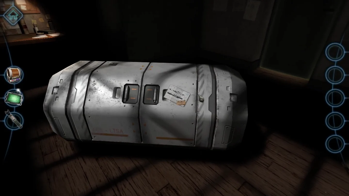
Open the white pod from both ends to find the handles that release it.
- Take the letter from the top of the white pod and read it.
- At one end of the pod, slide the two yellow latches outward and turn the big screw cover until it comes off; you get a big screw.
- Go to the other end and screw the big screw into the centre. The end plate comes off; take the handle inside.
- Duplicate the handle with the 3D printer. On top of the pod, insert both handles and pull them outward. The pod opens and the engine is set up in the workshop.
CHAPTER 6
Starting the Engine
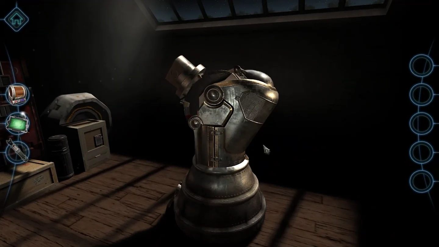
Open the engine's top cover and wake it up. Its ring works like the dome ring in Chapter 2.
- Use the magnetic screwdriver on the screw near the base of the engine and match its shape.
- Pick up the pliers from the floor next to the engine, then open the clasps on the sides. The top cover swings open on a ring of markers.
- This ring works like the one in Chapter 2: use the arrow controls to move the markers. Yellow markers push green ones and red markers block movement. Bring the green markers to the left and right sides of the ring. The ring glows white, the stone from Chapter 4 flies into the engine and the cover closes.
- Press the glowing amber button. The engine unfolds but starts leaking steam.
CHAPTER 6
Repairing the Engine
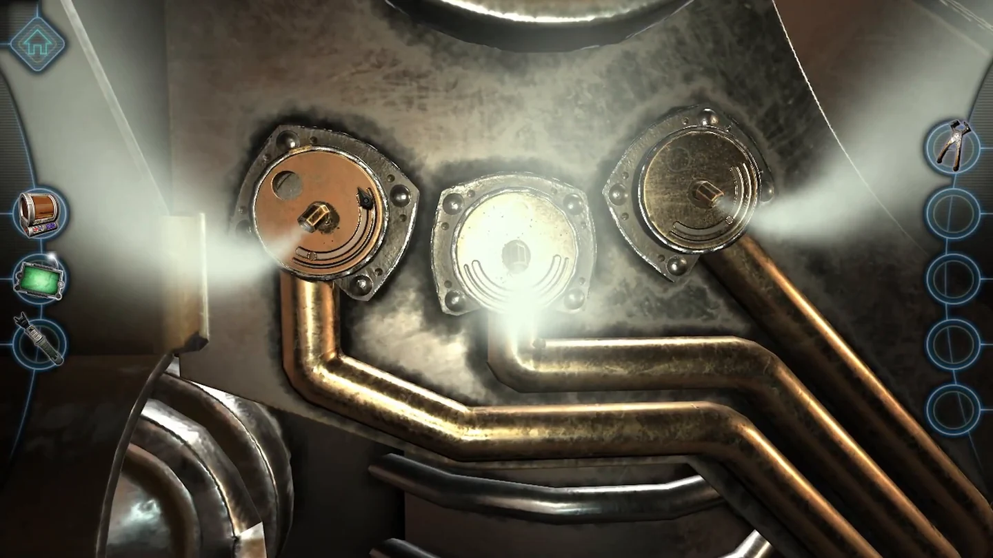
Stop the steam leak from inside, then balance the pressure with the six sliders.
- On the side where the steam escapes, turn the metal cover to uncover a small hole and insert the endoscope. Move forward until you see the backs of the three dials. Turn the right and middle dials so they touch, then close the endoscope and turn the left dial so it touches too. The steam stops.
- On the other side, set the six sliders so the gauge needle points at the green mark. From top to bottom: left, left, right, left, right, left. Then press the small red button below the gauge. An orange lever swings out below the panel; pull it down.
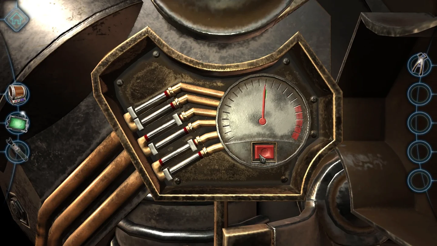
The sliders set and the needle on the green mark.
CHAPTER 6
The Hexagonal Core
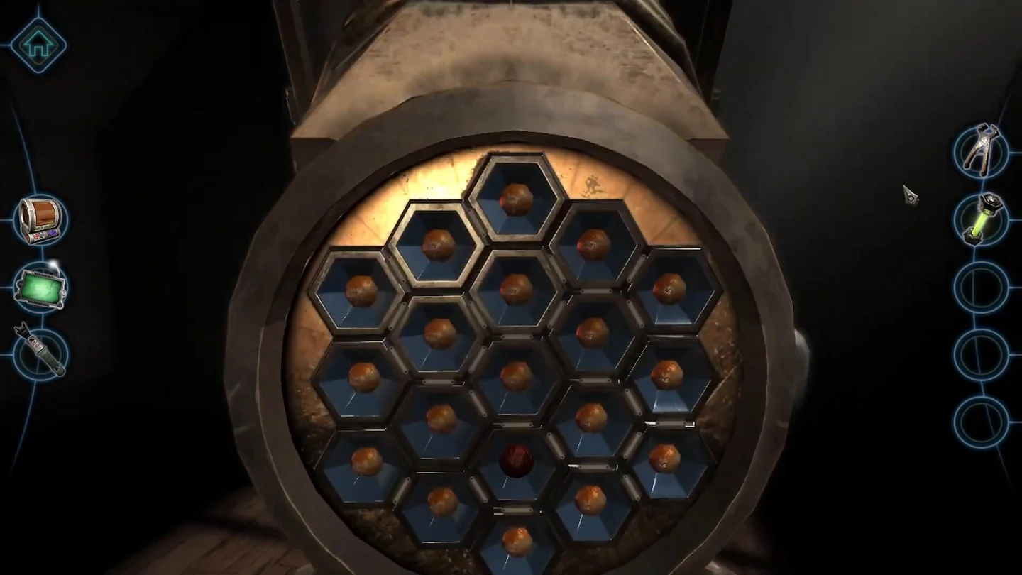
Replace the broken bar in the engine's hexagonal core. The light grid is solved by testing which cells spread light along the connectors.
- On the engine's neck, use the magnetic screwdriver on the screw marked with the radiation symbol beside the red button and match its shape. Then use the pliers to pull out the glowing radioactive bar.
- On the hexagonal grid at the back, remove the dark broken bar with the pliers and insert the radioactive bar. Connectors appear between the cells, and clicking a cell spreads light along its connectors. Think of the grid as five columns from left to right, holding 3, 4, 5, 4 and 3 cells, and count cells from the top of each column. Click these six cells: column 1 cell 3 (bottom), column 3 cell 5 (bottom), column 2 cell 2, column 3 cell 1 (top), column 5 cell 1 (top) and column 5 cell 3 (bottom). The entire grid lights up. Then press the glowing amber button again to run the engine and finish the chapter.
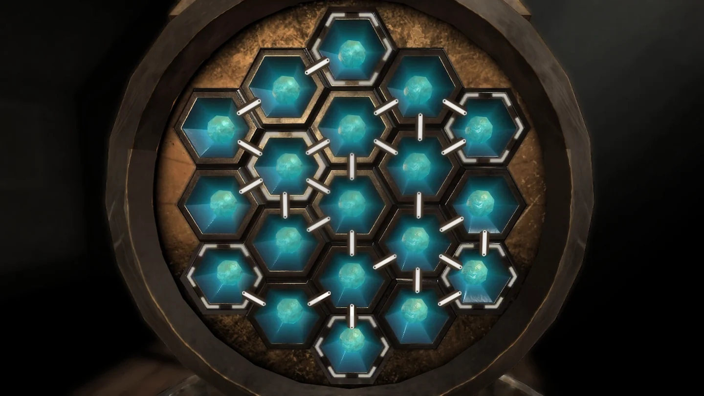
Solved: the entire grid lit. The six clicked cells have white outlines.
EVIDENCEEngine